
Page 18 - ITAtube Journal 1 2022
P. 18
18
Fig. 5 Checking key tooling dimensions
Technical Papers
close it might be to breaking. Surprisingly, higher elongations do not necessarily lead to higher loads.
Fundamentally the dimensional measure- ments are not very difficult but they will be found quite challenging due to the environ- ment in which the measurements have to be taken.
Note that it should be obvious by now that if the machine feed increment is changed after the tooling is manufactured then the entire calculation will not then be correct (assuming it was in the first place). Opera- tors who have not meet the computational
challenges will from time to time find adjusting the feed can produce improve- ments. Even the most proficient operators may find it necessary to make changes for issues like die wear mid-way through the life of the die. Note that it is it is easy to blame die wear when the problem can be elsewhere – roll bearings for instance.
More Sophistication
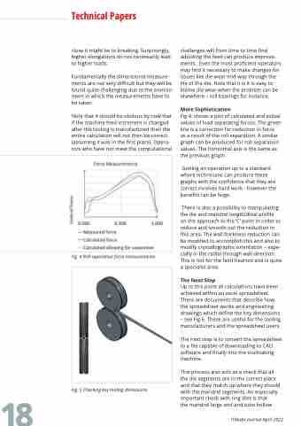
Fig 4. shows a plot of calculated and actual values of load separating forces. The green line is a correction for reduction in force
as a result of the roll separation. A similar graph can be produced for roll separation values. The horizontal axis is the same as the previous graph.
Getting an operation up to a standard where technicians can produce these graphs with the confidence that they are correct involves hard work - however the benefits can be huge.
There is also a possibility to manipulating the die and mandrel longitudinal profile
on the approach to the ‘C’ point in order to reduce and smooth out the reduction in this area. The wall thickness reduction can be modified to accomplish this and also to modify crystallographic orientation – espe- cially in the radial through wall direction. This is not for the faint hearted and is quite a specialist area.
The Next Step
Up to this point all calculations have been achieved within an excel spreadsheet. There are documents that describe how the spreadsheet works and engineering drawings which define the key dimensions – see Fig 6. These are useful for the tooling manufacturers and the spreadsheet users.
The next step is to convert the spreadsheet to a file capable of downloading to CAD software and finally into the toolmaking machine.
This process also acts as a check that all the die segments are in the correct place and that they match up where they should with the mandrel segments. An especially important check with ring dies is that
the mandrel large end and tube hollow
Fig. 4 Roll separation force measurements
ITAtube Journal April 2022
